![]()
Practice Test for 3V0-25.25 Certification Real 2026 Mock Exam
Prepare For Realistic 3V0-25.25 Dumps PDF - 100% Passing Guarantee
NEW QUESTION # 19
An architect has just deployed a new NSX Edge cluster in a VMware Cloud Foundation (VCF) fleet. The BGP peer between the NSX Tier-0 gateway and the top-of-rack routers is successfully up and stable.
* BGP Connection is established, but the NSX Tier-0 is not receiving a default route from the top-of-rack routers.
* Workloads inside NSX have no Internet access.
What could be the solution?
- A. There is no default route configured on the top-of-rack router for the Tier-0 gateway.
- B. The top-of-rack router receives a default route from Tier-0 gateway.
- C. Tier-0 gateway has a limit set too low for how many routes it can accept.
- D. Tier-0 gateway community settings are missing on the top-of-rack router configuration.
Answer: A
Explanation:
Comprehensive and Detailed 250 to 350 words of Explanation From VMware Cloud Foundation (VCF) documents:
In aVMware Cloud Foundation (VCF)deployment, establishing a stable BGP neighborship between the Tier-0 Gatewayand the physicalTop-of-Rack (ToR)switches is only the first step in enabling North-South connectivity. While the BGP state may show as "Established," this only confirms that the control plane handshake is complete and the peers are ready to exchange prefixes.
The primary reason for a lack of external connectivity in this scenario is that norouting informationis being shared. For workloads within the SDDC to reach the internet, the Tier-0 Gateway must have a path to external networks. In most enterprise VCF designs, the physical network (ToR) is expected to provide adefault route (0.0.0.0/0)to the Tier-0 Gateway.
If the Tier-0 is not receiving this route, the issue typically lies in the physical router's configuration. BGP does not automatically "originate" or "redistribute" a default route unless explicitly commanded to do so. On most physical network platforms (like Cisco, Arista, or Juniper), the administrator must specifically configure a
"default-originate" command or ensure a static default route exists in the physical RIB and is allowed to be advertised into the BGP session with the NSX Edge nodes.
Options A and C are unlikely to be the primary cause of a completely missing default route in a fresh deployment. Option B describes the inverse-where the virtual network tells the physical network how to find the internet-which is incorrect for a standard VCF consumer model. Therefore, verifying and enabling the default route advertisement on the physical ToR switchesis the verified solution to provide the Tier-0 with the necessary egress path for internet-bound workload traffic.
NEW QUESTION # 20
An NSX Manager cluster has failed. The administrator deployed a new NSX Manager using the latest version and attempted to restore from a backup, but the restore operation failed. What would an administrator do to recover the cluster?
- A. Use the NSX restore API instead of the UI.
- B. Use SDDC Manager to replace NSX Manager.
- C. Deploy an NSX Manager that matches the backup's build.
- D. Edit the backup passphrase to match the new build.
Answer: C
Explanation:
Comprehensive and Detailed 250 to 350 words of Explanation From VMware Cloud Foundation (VCF) documents:
A critical requirement for the backup and restore process inVMware NSX(and by extension, VCF) is version parity. The NSX Manager backup contains the database schema, configuration files, and state information specific to the version of the software that was running at the time the backup was taken.
When performing a restore into a "clean" environment, the NSX documentation explicitly states that the target NSX Manager appliancemust be of the exact same build versionas the appliance that generated the backup.
If an administrator attempts to restore a backup from version 4.1.x onto a newly deployed manager running version 4.2.x or 9.0 (as implies by "latest version"), the restore process will fail because the database schema of the newer version is incompatible with the older data structure.
In aVCF environment, whileSDDC Manager(Option B) handles the lifecycle and replacement of failed nodes, the actual "Restore from Backup" workflow is an NSX-native operation. If the entire cluster is lost, the recovery procedure involves:
* Identifying the build number from the backup metadata.
* Deploying a single "Discovery" node of that exact build.
* Pointing that node to the backup repository (SFTP/FTP).
* Executing the restore.
Once the primary node is restored to the correct version, the administrator can then add additional nodes to reform the cluster. Attempting to use the API (Option C) or changing the passphrase (Option A) will not bypass the fundamental requirement for version alignment between the backup file and the installed binary.
NEW QUESTION # 21
An administrator is investigating packet loss reported by workloads connected to VLAN segments in an NSX environment. Initial checks confirm:
* All VMs are powered on
* VLAN segment IDs are consistent across transport nodes
* Physical switch configurations are correct.
Which two NSX tools can be used to troubleshoot packet loss on VLAN Segments? (Choose two.)
- A. Live Flow
- B. Traceflow
- C. Flow Monitoring
- D. Activity Monitoring
- E. Packet Capture
Answer: B,E
Explanation:
Comprehensive and Detailed 250 to 350 words of Explanation From VMware Cloud Foundation (VCF) documents:
In a VMware Cloud Foundation (VCF) environment, troubleshooting packet loss requires tools that can provide visibility into both the logical and physical paths of a packet. When dealing specifically withVLAN segments(as opposed to Overlay segments), the traffic does not leave the host encapsulated in Geneve; instead, it is tagged with a standard 802.1Q header.
Traceflowis the primary diagnostic tool within NSX for identifying where a packet is being dropped. It allows an administrator to inject a synthetic packet into the data plane from a source (such as a VM vNIC) to a destination. The tool then reports back every "observation point" along the path, including switching, routing, and firewalling. If a packet is dropped by a Distributed Firewall (DFW) rule or a physical misconfiguration that wasn't caught initially, Traceflow will explicitly state at which stage the packet was lost.
Packet Captureis the second essential tool. NSX provides a robust, distributed packet capture utility that can be executed from the NSX Manager CLI or UI. This tool allows administrators to capture traffic at various points, such as the vNIC, the switch port, or the physical uplink (vmnic) of the ESXi Transport Node. By comparing captures from different points, an administrator can determine if a packet is reaching the virtual switch but failing to exit the physical NIC, or if return traffic is reaching the host but not the VM.
Options likeFlow MonitoringandLive Floware excellent for observing traffic patterns and session statistics (IPFIX), but they are less effective for pinpointing the exact cause of "packet loss" compared to the granular, packet-level analysis provided by Traceflow and Packet Capture.Activity Monitoringis typically used for endpoint introspection and user-level activity, which is irrelevant to Layer 2/3 packet loss troubleshooting.
NEW QUESTION # 22
An administrator is tasked to configure NSX Federation between separate VMware Cloud Foundation (VCF) Fleets. Which requirement must all sites meet before being added to a Global Manager (GM) for NSX Federation?
- A. All sites must use identical Tier-0 gateway BGP autonomous system numbers.
- B. All Sites must use the same VTEP VLAN and IP pools.
- C. All sites must be managed by the same VCF instance.
- D. All sites must have the same NSX version and build.
Answer: D
NEW QUESTION # 23
An administrator is tasked to enable users to configure an individual VPC, but not create subnets. What three NSX roles would the administrator assign to allow access without the ability to create subnets? (Choose three.)
- A. Security Operator
- B. Network Admin
- C. VPC Admin
- D. Security Admin
- E. Network Operator
Answer: A,C,E
Explanation:
Comprehensive and Detailed 250 to 350 words of Explanation From VMware Cloud Foundation (VCF) documents:
With the introduction of theVirtual Private Cloud (VPC)consumption model inVCF 9.0and late 5.x releases, Role-Based Access Control (RBAC) has become more granular to support true multi-tenancy. A VPC is designed to be a self-contained "container" for a department's or user's networking resources.
To meet the specific requirement where a user can configure aspects of an individual VPC but is restricted from creating new subnets (which involves modifying the underlying network CIDR blocks and IPAM), a combination of specific roles is required.
* VPC Admin:This is the primary role for the user within their assigned VPC. It allows the user to manage the overall VPC environment, including high-level settings and monitoring. However, the VPC Admin's power is often limited by the specific quotas and policies set by the Enterprise Admin.
* Security Operator:This role allows the user to view security configurations and policies without having the permission to modify the network fabric or create new infrastructure components like subnets. It provides the "read-only" visibility into the security posture of the VPC.
* Network Operator:Similar to the Security Operator, the Network Operator role provides visibility into the networking state-such as routing tables, segment status, and connectivity-without granting the
"Write" permissions required to provision new subnets or alter the network topology.
AssigningNetwork Admin(Option B) orSecurity Admin(Option A) would grant too much privilege, as these roles typically include the ability to create, delete, and modify subnets and firewall policies at a structural level. By combining theVPC Adminrole withOperator-level roles, the administrator ensures the user has the necessary context to manage their assigned resources while strictly adhering to the restriction against creating new network subnets.
NEW QUESTION # 24
Which two statements describe the recommended strategy for configuring and synchronizing security policies across Federated NSX sites? (Choose two.)
- A. Security policies should be defined locally on each LM and only synchronized manually by an administrator to prevent accidental conflicts.
- B. Consistency is achieved by ensuring all security groups have the exact same name on every Federated site's Local Manager (LM).
- C. Local Managers (LMs) can define local policies, but any global policies defined on the GM always take precedence over the local ones.
- D. Security policies, such as Distributed Firewall rules and security groups, must be defined as global policies on the Global Manager (GM).
- E. The Global Manager only synchronizes networking (L2/L3) configurations. Security rules must be configured separately on each site.
Answer: C,D
Explanation:
Comprehensive and Detailed 250 to 350 words of Explanation From VMware Cloud Foundation (VCF) documents:
NSX Federationis the cornerstone of multi-siteVMware Cloud Foundation (VCF)security, enabling administrators to maintain a consistent security posture across geographically dispersed data centers. The management of security in a Federated environment relies on a hierarchical relationship between theGlobal Manager (GM)andLocal Managers (LMs).
According to VMware documentation, the recommended strategy is to defineGlobal Security Policieson the Global Manager (Option B). When a security group or a Distributed Firewall (DFW) rule is created on the GM, it is automatically synchronized to all registered Local Managers. This ensures that a "Finance App" security policy is identical in AZ1 and AZ2. These global objects are identified by a specific tag in the local NSX Manager UI, indicating they are managed globally and cannot be modified locally.
Furthermore, NSX handles the coexistence of global and local rules through a specific evaluation order (Option D). In the NSX DFW category structure,Global Categories(managed by the GM) are evaluated beforeLocal Categories(managed by the LM). This ensures that corporate-wide security mandates (like
"Block All SSH to Management") defined at the GM level are enforced first and cannot be bypassed by localized site-level rules.
Option A is incorrect because manual naming consistency is prone to error and does not provide actual synchronization. Option C and E are incorrect as they contradict the fundamental purpose of Federation, which is to centralize management and automate synchronization to prevent configuration drift and security gaps. Therefore, defining policies on the GM and utilizing the inherent precedence of global rules is the verified design best practice for VCF Federation.
NEW QUESTION # 25
An administrator is troubleshooting intermittent connectivity failures between two workloads connected to NSX VLAN segments using Traceflow. In-band Network Telemetry (INT) has been enabled in the NSX Global Configuration. How does Traceflow identify issues in a VLAN network?
- A. Traceflow cannot be enabled to analyze VLAN network segments in NSX.
- B. Injects ICMP traffic into the data plane and observes the results in the control plane.
- C. Compares intended network state in the control plane with Tunnel End Point (TEP) keepalives in the data plane.
- D. Injects synthetic traffic into the data plane and observes the results in the control plane.
Answer: D
Explanation:
Comprehensive and Detailed 250 to 350 words of Explanation From VMware Cloud Foundation (VCF) documents:
InVMware Cloud Foundation (VCF)and NSX,Traceflowis a powerful diagnostic tool designed to provide visibility into the logical and physical path of a packet as it traverses the SDDC. Unlike standard ping or traceroute utilities that use real ICMP traffic from the Guest OS, Traceflow operates byinjecting synthetic trafficdirectly into the data plane at the source point (usually the vNIC of a Virtual Machine).
When Traceflow is initiated, the NSX Manager creates a "trace packet" that mimics the characteristics of the traffic being investigated (such as TCP, UDP, or ICMP with specific headers). This synthetic packet is marked with a special metadata tag. As the packet moves through the virtual switches (VDS), logical routers (DR/SR), and distributed firewalls (DFW) on the ESXi Transport Nodes, each component recognizes the tag and reports an "observation" back to theCentral Control Plane (CCP). The CCP then aggregates these observations and presents them in the NSX Manager UI.
ForVLAN-backed segments, Traceflow functions similarly to how it works on Overlay segments. It tracks the packet as it is switched at Layer 2 and processed by any applicable distributed services. The inclusion of In-band Network Telemetry (INT)in modern VCF versions (5.x and 9.0) enhances this by allowing the synthetic packet to collect telemetry data from INT-capable physical switches in the fabric. This provides a
"hop-by-hop" view that includes both the virtual and physical segments of the journey.
Option A is incorrect because Traceflow is not limited to ICMP; it can simulate various protocols. Option C is incorrect as Traceflow fully supports VLAN segments. Option D is incorrect as it describes a state- comparison mechanism rather than the active injection process that defines Traceflow. Therefore, the injection of synthetic traffic to observe data plane behavior via the control plane is the verified mechanism.
NEW QUESTION # 26
An administrator is attempting to confirm the successful transmission between an internal VM to an external destination.
An ICMP request packet is being sent from Sa-transit-web-01 to the Student Desktop in the diagram.
Drag and Drop the commands output into their appropriate originating NSX object.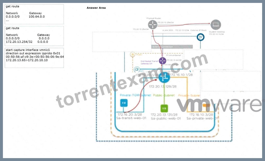
Answer:
Explanation: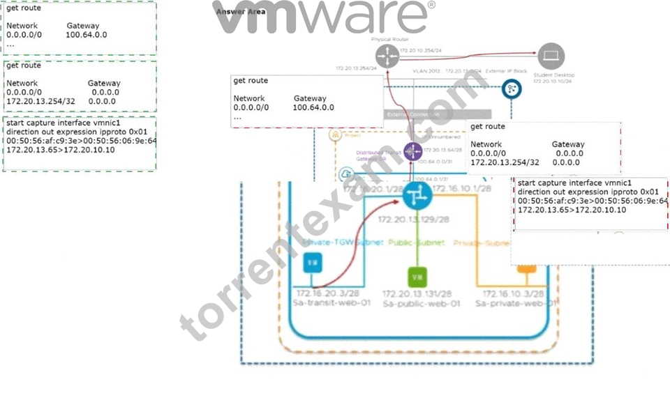
Explanation: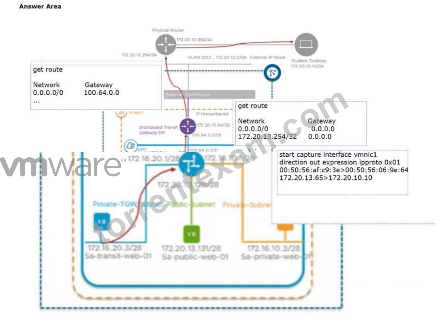
In a modernVCF 9.0environment using theVirtual Private Cloud (VPC)model, North-South traffic follows a specific hierarchical path. When a VM, such asSa-transit-web-01, initiates an ICMP request to an external destination (the Student Desktop), the packet must traverse the VPC's internal routing before exiting to the physical network.
The first hop is theVPC Tier-1 Gateway. This gateway manages the localized subnets within the VPC. In this architecture, the VPC Tier-1 is typically configured with a default route ($0.0.0.0/0$) pointing to the Transit Gateway (TGW). The gateway address 100.64.0.0 represents the provider-side interface of the Router Link connecting the VPC to the Transit Gateway. Thus, the command output showing the default route to 100.64.0.0 belongs to the VPC Gateway.
The second hop is theDistributed Transit Gateway DR. The Transit Gateway acts as the aggregation point for multiple VPCs and provides the bridge to the physical datacenter fabric. The command output for this object shows a default route with a gateway of 0.0.0.0, indicating it is directly peered or using a specific unnumbered interface to reach the physical router. Additionally, it identifies the specific physical router IP (172.20.13.254/32) as a known local next-hop, which is a common characteristic of the Transit Gateway's forwarding table when performing North-South transitions.
Finally, theTransport Node (ESXi Host)is where the physical packet capture occurs. As the packet exits the virtual environment, it is placed on a physical uplink (vmnic1). The packet capture output confirms the transformation of the traffic: it shows the source IP of the VM (or its translated NAT address 172.20.13.65) reaching out to the destination 172.20.10.10. The inclusion of ipproto 0x01 (ICMP) and the specific MAC addresses confirms that the packet has successfully traversed the NSX overlay and is now a standard Ethernet frame on the physical wire.
NEW QUESTION # 27
An administrator is troubleshooting BGP flapping in a VMware Cloud Foundation (VCF) 9 environment. A Tier-0 Gateway is running in Active/Active mode with two Edge nodes. BFD is enabled on the eBGP sessions to the upstream routers. Each Edge node uses its own uplink IP for BGP. After some network maintenance, one BGP session starts flapping every few minutes. The other BGP sessions stay stable. On the affected Edge node, the command get bfd-sessions shows:
* State: Down
* Diag: Detect Time Expired
Symptoms:
* The upstream router also shows the BFD session as Down with control Detection Time Expired.
* There are no interface errors, no packet loss for normal traffic, and clearing the BFD session temporarily brings it back up - but it flaps again after few minutes.
What is the root cause?
- A. The Edge nodes are undersized and are experiencing high contention on CPU and drops BFD packets.
- B. BFD is configured in echo mode on the upstream routers.
- C. BFD timers are mismatched between Tier-0 Gateway and the upstream routers.
- D. The MTU does not match on the end-to-end between Tier-0 Gateway and upstream routers.
Answer: D
Explanation:
Comprehensive and Detailed 250 to 350 words of Explanation From VMware Cloud Foundation (VCF) documents:
In aVMware Cloud Foundation (VCF)environment, particularly with the high-performance requirements of North-South routing,BGPandBFD (Bidirectional Forwarding Detection)are used in tandem to ensure rapid failure detection. A common but subtle issue in fresh or modified environments is anMTU (Maximum Transmission Unit) mismatchon the physical or virtual uplinks.
When BGP establishes a neighborship, it initially exchanges small keepalive packets. These small packets easily pass through interfaces even if there is an MTU mismatch (e.g., the Edge is set to 9000 bytes but a physical switch in the path is limited to 1500 bytes). However, once the BGP state reaches "Established," the routers begin exchanging full routing tables. TheseBGP Updatepackets are often large and will be fragmented or dropped if they exceed the MTU of any hop in the path.
The symptom described-where the session is stable for a few minutes (during the initial handshake) and then flaps-is the hallmark of an MTU issue. The "Detect Time Expired" diagnostic in BFD occurs because the BGP hold timer expires when it fails to receive the large update packets, or the BFD packets themselves are delayed/lost due to the congestion caused by retrying large, failed transmissions. According to VMware NSX troubleshooting documentation, if pings (small packets) succeed but the BGP session fails specifically when traffic load or route counts increase, the MTU should be the first setting verified.
VCF 9.0 and 5.x designs mandate consistent MTU settings (typically9000 MTUfor the overlay and at least
1500+for the uplinks) across the entire path, including the virtual switch (VDS), the Edge VM vNICs, and the physical ToR switches. A mismatch here prevents the completion of the BGP state machine's full synchronization, leading to the cyclic "flapping" observed by the administrator.
NEW QUESTION # 28
An administrator was asked to explain the characteristic and requirements of Centralized Connectivity Mode which is planned to be configured in one of the workload domains in VMware Cloud Foundation (VCF) environment.
Drag and drop four options from the Options list on the left and place them into the Centralized Connectivity Mode on the right in any order. (Choose four.)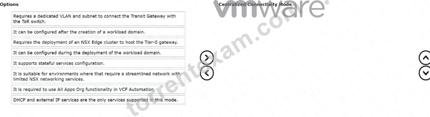
Answer:
Explanation: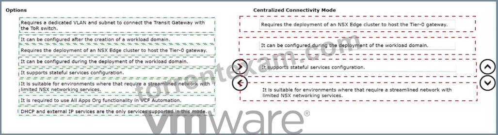
Explanation:
* Requires the deployment of an NSX Edge cluster to host the Tier-0 gateway.
* It can be configured during the deployment of the workload domain.
* It supports stateful services configuration.
* It is suitable for environments that require a streamlined network with limited NSX networking services.
InVMware Cloud Foundation (VCF) 9.0, the networking architecture introduces specialized connectivity modes to cater to different organizational needs, withCentralized Connectivity Modebeing a primary option for streamlined deployments. This mode is fundamentally anchored to the physical infrastructure via localized resources rather than distributed components across the entire cluster.
The most critical technical requirement for this mode is that itrequires the deployment of an NSX Edge cluster to host the Tier-0 gateway. Unlike distributed models, centralized connectivity funnels North-South traffic through specific Edge nodes that serve as the demarcation point between the virtual overlay and the physical Top-of-Rack (ToR) switches. This centralization is what enables the next key characteristic: it supports stateful services configuration. Because traffic is anchored to specific Service Routers (SR) on Edge nodes, stateful operations such as NAT, Load Balancing, and stateful firewalls can maintain session persistence, which is not natively possible in a purely distributed Active/Active ECMP environment without specialized configuration.
From a lifecycle perspective, this mode is highly integrated into the SDDC Manager workflows andcan be configured during the deployment of the workload domain. This allows architects to define the networking posture of a new domain at "Day 0," ensuring that the necessary Edge resources and Tier-0/Tier-1 hierarchies are provisioned automatically to meet the domain's specific requirements.
Finally, Centralized Connectivity Modeis suitable for environments that require a streamlined network with limited NSX networking services. It provides a "cloud-lite" approach to networking, offering the necessary isolation and security of NSX without the complexity of managing a full-scale distributed fabric.
This makes it an ideal choice for smaller workload domains, specialized labs, or legacy application environments that do not require the massive scale of a distributed transit gateway but still need robust stateful security and simplified North-South egress.
NEW QUESTION # 29
Which of the following statements is true when configuring Remote Tunnel End Points (RTEPs) with NSX Federation?
- A. The default MTU for the RTEP network is 1500.
- B. DHCP must be used to assign IP addresses to the RTEP.
- C. TEP and RTEP networks must use separate physical NICs.
- D. RTEP needs to be configured on only one edge node.
Answer: A
Explanation:
Comprehensive and Detailed 250 to 350 words of Explanation From VMware Cloud Foundation (VCF) documents:
In anNSX Federationdeployment, which is a key component of multi-siteVMware Cloud Foundation (VCF)architectures, theRemote Tunnel End Point (RTEP)is used specifically for inter-site communication.
While standard TEPs (Tunnel End Points) handle overlay traffic within a single site (East-West), RTEPs facilitate the encapsulation of traffic that needs to traverse the Layer 3 network between different geographical locations.
A critical design consideration for RTEP is theMaximum Transmission Unit (MTU). Within a local VCF site, jumbo frames (MTU 1600 or 9000) are highly recommended and often required for the Geneve overlay to account for encapsulation overhead. However, when traffic leaves a site to travel over a WAN or a provider's long-haul network, it often encounters physical infrastructure that only supports the standard internet MTU of1500 bytes.
According to VMware's "NSX Federation Design Guide," the default MTU setting for the RTEP configuration is1500. This ensures that inter-site traffic can pass through standard routers and VPNs without being dropped due to size constraints. If the inter-site physical links support larger frames, this value can be increased, but 1500 remains the baseline compatible default.
Regarding the other options:Ais incorrect because TEP and RTEP can share the same physical N-VDS and physical NICs (pNICs) by using different VLANs or subnets.Bis incorrect because every Edge node within a cluster that is participating in the Federation must have an RTEP configured to ensure high availability and proper traffic processing for global segments.Dis incorrect as IP addresses for RTEPs are typically assigned viaStatic IP Poolsmanaged within NSX to ensure consistency and ease of tracking across sites, rather than relying on DHCP which is less common in data center backbone configurations.
NEW QUESTION # 30
An architect is designing a VMware Cloud Foundation (VCF) solution. The following information was gathered during the assessment phase:
* There is a critical application used by the Finance Team.
* The critical application has an availability and recoverability SLA of 99.999%.
* The critical application is sensitive to network changes.
Which two configurations should the architect include in their design? (Choose two.)
- A. Configure Tier-1 gateway for eBGP and ECMP.
- B. Configure Tier-0 gateway for eBGP and ECMP.
- C. Configure multiple static routes on Tier-1 gateway.
- D. Enable BFD on the Tier-0 gateway.
- E. Install and configure hosts with 100Gbps physical NICs.
Answer: B,D
Explanation:
Comprehensive and Detailed 250 to 350 words of Explanation From VMware Cloud Foundation (VCF) documents:
Designing for "five nines" (99.999%) availability in aVMware Cloud Foundation (VCF)environment requires a network architecture that minimizes convergence time and eliminates single points of failure. For a critical application sensitive to network changes, the connection between the virtualized SDDC and the physical network must be highly resilient and capable of near-instantaneous failover.
TheTier-0 Gatewayis the primary interface for North-South traffic. To meet high availability requirements, the Tier-0 should be configured witheBGP (External Border Gateway Protocol)to peer with physical Top- of-Rack (ToR) switches. By enablingECMP (Equal Cost Multi-Pathing), the architect allows the Tier-0 to utilize multiple active paths to the physical world simultaneously. This not only increases available bandwidth but also ensures that if one physical link or router fails, traffic is immediately redistributed across the remaining active paths without a protocol timeout.
To complement ECMP,BFD (Bidirectional Forwarding Detection)is essential. While BGP's default keepalive and hold timers are often measured in seconds (typically 60 and 180 seconds, respectively), BFD provides sub-second failure detection. In a VCF environment, BFD operates as a lightweight "heartbeat" between the Tier-0 Edge nodes and the physical ToR routers. If a path fails, BFD detects it within milliseconds and notifies BGP to pull the failed path from the routing table. This combination ofeBGP/ECMP for path redundancy andBFDfor rapid detection is the verified standard for VCF designs requiring extreme uptime and sensitivity to network disruptions.
Static routes (Option A) are unsuitable for high-availability designs as they lack dynamic failure detection.
While 100Gbps NICs (Option E) provide bandwidth, they do not inherently provide the protocol-level resilience needed to meet a 99.999% SLA.
NEW QUESTION # 31
When attempting to deploy or expand an edge cluster from an administrator encounters a failure: "Failed to validate the BGP Route Distribution". Prior to calling support, the administrator attempts to troubleshoot the issue. How should the administrator troubleshoot this issue?
- A. Log into the NSX manager and examine the nsxapi.log for errors.
- B. Log into the vCenter and verify there are no errors or warnings from the NSX manager.
- C. Log into the edge node of the Tier-0 being deployed and check the routes being learnt.
- D. Log into the Tier-1 router to verify that route distribution is being enabled.
Answer: C
Explanation:
Comprehensive and Detailed 250 to 350 words of Explanation From VMware Cloud Foundation (VCF) documents:
InVMware Cloud Foundation (VCF), theSDDC Managerautomates the deployment and expansion ofNSX Edge Clusters. As part of the automated workflow, particularly in VCF 4.x, 5.x, and 9.0, a "Verify BGP Route Distribution" task is executed. This task is a validation check designed to ensure that the newly deployed or expanded Edge nodes are successfully peering with the physical Top-of-Rack (ToR) switches and, more importantly, are actually receiving routes.
According to VMware/Broadcom technical documentation (specificallyKB 388351), the workflow expects to see at least one route (often the default route or specific physical prefixes) learned via BGP from the northbound peer. If the Edge nodes establish a BGP session but the physical switches are not advertising any routes (or are only advertising routes that the Edge ignores due to filters), the SDDC Manager validation fails with the error "Failed to validate the BGP Route Distribution".
The verified troubleshooting step is tolog into the CLI of the Edge nodeidentified in the failure. Using the command get route bgp from within the Tier-0 Service Router (SR) VRF context allows the administrator to see the current Routing Information Base (RIB). If the table is empty or only contains internal "ISR" (Inter- SR) routes, it confirms that the physical network is not providing the expected advertisements. This allows the administrator to correct the BGP advertisement settings on the physical ToR switches-such as enabling default-originate-and then simply "Resume" the task in SDDC Manager without needing to redeploy the entire cluster.
NEW QUESTION # 32
An administrator is investigating reports that several Virtual Machines (VMs) deployed on an NSX virtual network segment are dropping packets. To troubleshoot the issue the administrator has attached two test VMs to the virtual network in order to inspect the packets sent between the two test VMs. What tool will allow the administrator to analyze the packet flow?
- A. Flows Monitoring in the VCF Operations UI.
- B. Live Traffic Analysis in the NSX Manager UI.
- C. Port Mirroring in the NSX Manager UI.
- D. Traceflow in the NSX Manager UI.
Answer: D
Explanation:
Comprehensive and Detailed 250 to 350 words of Explanation From VMware Cloud Foundation (VCF) documents:
In aVMware Cloud Foundation (VCF)environment, pinpointing the exact location of packet drops within the software-defined data center requires tools that can see into the logical forwarding pipeline. While traditional networking tools like pings only provide a "binary" up/down status,Traceflowis the definitive diagnostic tool within theNSX Manager UIfor deep packet path analysis.
Traceflow works by injecting a synthetic "trace packet" into the data plane, originating from a source vNIC of a specific VM. This packet is uniquely tagged so that every NSX component it touches-including the Distributed Switch (VDS), Distributed Firewall (DFW) rules, Distributed Routers (DR), and Service Routers (SR) on Edge nodes-reports back an observation.
When an administrator observes packet drops, Traceflow provides a step-by-step visualization of the packet's journey. If the packet is dropped, Traceflow will explicitly identify the component responsible. For example, it might show that the packet was "Dropped by Firewall Rule #102" or "Dropped by SpoofGuard." It can also identify if the packet was lost during Geneve encapsulation or at the physical uplink interface.
Option A (Flows Monitoring) is useful for long-term traffic patterns and session statistics but lacks the packet- level "hop-by-hop" granular detail provided by Traceflow. Option C (Port Mirroring) is used to send a copy of traffic to a physical or virtual appliance (like a Sniffer or IDS), which is more complex to set up and usually reserved for external deep packet inspection (DPI) rather than internal path troubleshooting. Option D (Live Traffic Analysis) is a broader term, but within the context of the NSX troubleshooting toolkit for "packet flow analysis" between two points,Traceflowis the verified and documented solution for verifying the logical path and identifying drops.
NEW QUESTION # 33
When using a DHCP Relay on a segment, which design restriction must be considered?
- A. DHCP Relay service is available to all the other segments in the network.
- B. DHCP client requests cannot be relayed to the external DHCP servers.
- C. DHCP settings, DHCP options, and static bindings cannot be configured on the segment.
- D. DHCP settings, DHCP options, and static bindings can be configured on the segment.
Answer: C
Explanation:
Comprehensive and Detailed 250 to 350 words of Explanation From VMware Cloud Foundation (VCF) documents:
InVMware Cloud Foundation (VCF)networking, IP address management within an NSX segment can be handled by either the native NSX DHCP server or by an external DHCP server. When an administrator chooses to use an existing external corporate DHCP infrastructure, they must configure aDHCP Relayon the logical segment.
The DHCP Relay works by intercepting the initial DHCP Discover broadcast from a workload VM and forwarding it (as a unicast packet) to the specified IP address of the external DHCP server. However, NSX enforces a strict mutual exclusivity in its configuration logic to prevent conflicts and unpredictable address assignments.
According to the "NSX-T Data Center Administration Guide," once a segment is configured to use aDHCP Relay profile, the native NSX DHCP capabilities for that specific segment are disabled. This means that DHCP settings, DHCP options, and static bindings cannot be configured on that segment(Option A). All such configurations, including IP reservations and scope options (like DNS or NTP), must be managed centrally on the external DHCP server.
Option C is incorrect because the UI will physically grey out or prevent the entry of native DHCP parameters once the Relay is selected. Option B is incorrect as the primary purpose of a Relay is precisely to forward requests to external servers. Option D is incorrect because a DHCP Relay is configured on a per-segment or per-gateway basis; it is not a "global" service that automatically covers all other segments in the network.
Therefore, the architectural trade-off when choosing a Relay is the shift of all management and binding logic to the external physical or virtual DHCP appliance.
NEW QUESTION # 34
An administrator is troubleshooting an issue where workloads connected to a Tier-1 Gateway named T1-App can no longer reach external North/South destinations.
* The Tier-1 is connected to an Active/Standby Tier-0 Gateway named T0-Prod.
Symptoms observed:
* VMs on segments attached to T1-App can ping each other.
* VMs on T1-App cannot reach any external IP outside T0-Prod.
* From a VM on the segment, ping to the T1-App Distributed Router (DR) IP succeeds.
* Ping from the VM to the T1-App Service Router (SR) fails.
* The Edge cluster hosting the T1-App SR shows both Edge nodes Up and Healthy.
* No failover has occurred - the same Edge node is still shown as Active for T1-App.
What is the most likely cause of this issue?
- A. Route advertisement from T1-App to T0-Prod for 100.64.x.x/31 is disabled.
- B. Static default route is missing on the Tier-1 DR component.
- C. The overlay network between DR and SR has an MTU mismatch.
- D. Localized control plane is enabled on the Tier-1 causing the SR to remain admin-down.
Answer: C
Explanation:
Comprehensive and Detailed 250 to 350 words of Explanation From VMware Cloud Foundation (VCF) documents:
In theNSXmulti-tier routing architecture used by VCF, aTier-1 Gatewayis composed of two primary components: theDistributed Router (DR)and theService Router (SR). The DR runs as a kernel module on every ESXi host in the transport zone, facilitating East-West traffic. The SR resides on the NSX Edge nodes and provides centralized services like North-South connectivity and stateful services.
Communication between the DR (on the ESXi host) and the SR (on the Edge node) occurs over a hidden internal segment known as theRouter Link. This link is encapsulated inGenevejust like VM-to-VM traffic.
When a VM attempts to reach an external destination, the packet is first routed by the DR on the local host.
The DR then encapsulates the packet and sends it across the overlay to the TEP (Tunnel Endpoint) of the Edge node hosting the SR.
If theMTU (Maximum Transmission Unit)is misconfigured on the physical network or the virtual switches, large encapsulated packets will be dropped. However, small packets (like pings between VMs on the same host) might still succeed. In this scenario, the fact that the VM can ping the local DR butcannot reach the SR
-and therefore cannot reach external networks-points to a failure in the transport between the host and the Edge.
If the Geneve-encapsulated packet containing the ping request to the SR's internal interface exceeds the physical network's MTU, it will fail. Since VCF 5.x/9.0 requires a minimum MTU of1600(ideally9000) for the overlay to account for the Geneve overhead, a mismatch anywhere in the fabric will break the DR-to-SR
"backplane" communication. This prevents the Tier-1 from passing any traffic to its Tier-0 uplink, effectively isolating the workloads from North-South traffic.
NEW QUESTION # 35
An administrator created a new Tier-1 Gateway and is attempting to change the connected gateway for a deployed segment to use the new gateway. In the UI, when the administrator clicks the Connected Gateway dropdown, the new Tier-1 gateway is not shown as an available gateway. What would prevent the new Tier-1 gateway from showing in the list of available gateways?
- A. The Tier-1 Gateway and NSX Segment are in different transport zones.
- B. The Tier-1 Gateway connectivity policy is set to "None".
- C. The Tier-1 Gateway is not connected to an NSX Edge Cluster.
- D. The Tier-1 Gateway and NSX Segment are connected to different Tier-0 Gateways.
Answer: A
Explanation:
Comprehensive and Detailed 250 to 350 words of Explanation From VMware Cloud Foundation (VCF) documents:
InVMware Cloud Foundationnetworking, the relationship between segments and gateways is governed by the underlyingTransport Zone (TZ)configuration. A Transport Zone defines the potential span of a virtual network-specifically, which hosts and edges can participate in that network.
When an administrator creates anNSX Segment, they must associate it with a specific Transport Zone (either Overlay or VLAN). Similarly, when aTier-1 Gatewayis created, its reach is determined by the Transport Zones available on the Transport Nodes (Edges and ESXi hosts) where it is instantiated. For a Segment to be attached to a Tier-1 Gateway, both objectsmust reside within the same Transport Zone.
If the Segment was created in "Overlay-TZ-01" but the new Tier-1 Gateway is only associated with "Overlay- TZ-02" (or if one is in a VLAN TZ and the other in an Overlay TZ), the NSX Manager UI will filter out the incompatible gateway to prevent an invalid configuration. The logical switch (Segment) cannot bind to a gateway if they do not share a common broadcast or encapsulation domain defined by the Transport Zone.
Option A is incorrect because a Tier-1 Gateway does not strictlyrequirean Edge Cluster unless it is providing stateful services (like NAT, LB, or Firewall). It can exist purely as a distributed component on the hypervisors. Option B (Connectivity Policy) determines if the T1 advertises routes to the T0, but it doesn't prevent a segment from connecting to it. Option D is also incorrect, as a Tier-1 Gateway can be moved between Tier-0s, or even exist without a Tier-0 connection initially. Therefore, theTransport Zone mismatch is the fundamental architectural barrier preventing the gateway from appearing in the selection list.
NEW QUESTION # 36
The administrator is implementing a multi-location VMware Cloud Foundation (VCF) environment. The design requires centralized security and networking policies across multiple VCF instances. What action must the administrator take to satisfy the requirements?
- A. Deploy a Global Manager cluster manually.
- B. Use SDDC Manager to deploy a Global Manager cluster.
- C. Deploy a Local Manager (LM) cluster using VCF Operations.
- D. Use VCF Installer to deploy a Local Manager (LM) cluster.
Answer: B
Explanation:
Comprehensive and Detailed 250 to 350 words of Explanation From VMware Cloud Foundation (VCF) documents:
In aVMware Cloud Foundation (VCF)Multi-Site or Multi-Instance design, the requirement for "centralized security and networking policies" is fulfilled byNSX Federation. Federation introduces theGlobal Manager (GM), which provides a single pane of glass to manage objects that span across different VCF sites.
Historically, in early versions of NSX-T, Global Managers were deployed manually. However, within the VCF framework (VCF 4.x, 5.x, and 9.0), the deployment and lifecycle management of theGlobal Manager clusterare fully integrated intoSDDC Manager. According to the VCF Design Guide and "Deploying and Configuring NSX Federation" documents, the verified best practice is to use the SDDC Manager UI or API to trigger the GM deployment.
When an administrator usesSDDC Manager(Option C), the process is automated: SDDC Manager deploys the appliances, configures the virtual IP (VIP), handles the certificate management, and ensures that the GM is properly integrated into the VCF Bill of Materials (BOM). This automation is critical for maintaining supportability, as it ensures the GM version is perfectly aligned with the Local Managers (LMs) already present in the Management and Workload domains.
Option A is discouraged because manual deployments lead to configuration drift and issues with future automated upgrades. Option B is incorrect as VCF Operations is for monitoring, not deployment. Option D is incorrect because theVCF Installeris primarily used for the initial "bring-up" of the Management Domain; subsequent management components like GMs are handled by the SDDC Manager once the initial site is active. Thus, SDDC Manager is the authoritative tool for deploying the Global Manager cluster in a VCF multi-location environment.
NEW QUESTION # 37
An administrator is enabling IPv6-to-IPv4 communication for workloads hosted in an NSX environment. The workloads use IPv6-only addressing, but the external systems they must reach are IPv4-only. To provide this translation service, the administrator decides to configure NAT64. Which two following characteristics about NAT64 are true? (Choose two.)
- A. NAT64 is supported on Tier-0 and Tier-1 gateways.
- B. NAT64 requires the Tier-1 gateway to be configured in active-active mode.
- C. NAT64 requires the Tier-1 gateway to be configured in active-standby mode.
- D. NAT64 is stateless and requires gateways to be deployed in active-standby mode.
- E. NAT64 is supported on Tier-1 gateways only.
Answer: A,C
Explanation:
Comprehensive and Detailed 250 to 350 words of Explanation From VMware Cloud Foundation (VCF) documents:
As organizations modernize their infrastructure withVCF 5.x and 9.0, IPv6 adoption becomes more prevalent.
NAT64is a critical transition technology that allows IPv6-only hosts to communicate with IPv4-only resources by translating the packet headers.
In NSX, NAT64 is astateful service. Stateful services in the NSX architecture require a centralized point of processing to maintain the session state table. Because of this requirement, any gateway (Tier-0 or Tier-1) providing NAT64 servicesmust be configured in Active-Standby high availability mode. In Active-Active mode, asymmetric return traffic could hit a different Edge node that does not have the session information, causing the translation to fail. This is a fundamental design constraint for stateful NAT in NSX.
Furthermore, VMware NSX documentation specifies that NAT64 is a flexible service that can be implemented at multiple tiers of the logical routing hierarchy. It issupported on both Tier-0 and Tier-1 gateways. The choice of where to place the NAT64 service depends on the design requirements: placing it on the Tier-1 gateway allows for tenant-specific translation and offloads the Tier-0, while placing it on the Tier-0 provides a centralized translation point for all connected segments.
Option A is incorrect because NAT64 in NSX is stateful, not stateless. Option C is incorrect because it is not limited to Tier-1. Option E is incorrect because Active-Active mode does not support the stateful nature of the NAT64 engine. Consequently, the correct architecture requires anActive-Standbyconfiguration on either a Tier-0 or Tier-1gateway to properly facilitate the translation between the IPv6 workloads and the IPv4 external world.
NEW QUESTION # 38
The administrator must configure Border Gateway Protocol (BGP) on the Tier-0 Gateway to establish neighbor relationships with upstream routers. Which two statements describe the Border Gateway Routing Protocol (BGP) configuration on a Tier-0 Gateway? (Choose two.)
- A. EIGRP is configured by default.
- B. Can be used as an Exterior Gateway Protocol.
- C. The network is divided into areas that are logical groups.
- D. It supports a 4-byte autonomous system number.
Answer: B,D
Explanation:
Comprehensive and Detailed 250 to 350 words of Explanation From VMware Cloud Foundation (VCF) documents:
In the architecture ofVMware Cloud Foundation (VCF)and its networking component, NSX, theTier-0 Gatewayserves as the critical demarcation point between the virtualized overlay network and the physical infrastructure. To facilitate this communication, BGP is the industry-standard protocol utilized.
BGP is fundamentally designed as anExterior Gateway Protocol (EGP). While it can be used internally (iBGP), its primary role in a VCF deployment is to exchange routing information between the SDDC and the physical Top-of-Rack (ToR) switches or core routers (eBGP). This allows the physical network to learn about the virtual subnets (overlay segments) and allows the virtual environment to receive a default route or specific external prefixes. This confirms that BGP is utilized as an EGP in these designs.
Furthermore, as global IP networking has evolved, the traditional 2-byte Autonomous System (AS) numbers (ranging from 1 to 65,535) were found to be insufficient for the number of organizations requiring them.
Modern NSX versions integrated into VCF 5.x and 9.0 fully support4-byte Autonomous System numbers (ranging from 1 to 4,294,967,295). This support is essential for service providers and large enterprises that have been assigned 4-byte ASNs by regional internet registries.
Option A is incorrect because EIGRP is a proprietary Cisco protocol and is not used by NSX. Option C describes OSPF (Open Shortest Path First), which uses "Areas," whereas BGP uses "Autonomous Systems." Therefore, the ability to act as an EGP and support for 4-byte ASNs are the verified characteristics of BGP within the VCF networking stack.
NEW QUESTION # 39
An administrator is configuring NSX resource sharing to allow shared access to multiple resources in the default space.
By default, which user role owns the shared resources for the default space?
- A. Network Admin
- B. Security Admin
- C. Enterprise Admin
- D. Project Admin
Answer: C
Explanation:
In NSX Multi-Tenancy (Projects), theEnterprise Adminacts as the provider-level administrator who owns global objects in the default space. This ensures central control over resources that are shared across different projects.
NEW QUESTION # 40
An administrator encountered a failure with one of the NSX Managers in a VCF Fleet. The administrator has successfully re-deployed an NSX Manager from SFTP backups. However, after replacing the failed manager node, the new node joins successfully, but the cluster status remains "Degraded".
* The get cluster status command on the leader still shows the old UUID with state "REMOVED".
What is the command to resolve the issue?
- A. delete node <old-uuid>
- B. detach node <new-uuid>
- C. detach node <old-uuid> then delete node <old-uuid>
- D. detach node <old-uuid>
Answer: D
Explanation:
Comprehensive and Detailed 250 to 350 words of Explanation From VMware Cloud Foundation (VCF) documents:
In aVMware Cloud Foundation (VCF)environment, the NSX Management Cluster consists of three nodes to ensure high availability and quorum. When a single node fails and is subsequently replaced-either through a manual deployment or an orchestrated recovery viaSDDC Manager-the internal database (Corfu) and the cluster manager must be updated to reflect the current members of the cluster.
When a node is lost or manually deleted from vCenter without being properly decommissioned through the NSX API or CLI, the remaining "Leader" node retains the metadata and theUUIDof that missing member.
Even after a new node joins the cluster and synchronizes data, the cluster state often remains in a"Degraded" status because the control plane still expects a response from the original, failed UUID.
According to NSX troubleshooting and recovery guides, the specific command to purge a stale or defunct member from the cluster configuration isdetach node <UUID>. This command must be executed from the CLI of the current Cluster Leader. By running detach node <old-uuid>, the administrator instructs the cluster manager to permanently remove the record of the failed node from the management plane's membership list.
Option B and C are incorrect because "delete node" is not the primary CLI command used for cluster membership cleanup; "detach" is the specific primitive required to break the logical association. Option A would remove the healthy new node, worsening the situation. Once the stale UUID is detached, the cluster status should transition from "Degraded" to "Stable" as it no longer tries to communicate with the non- existent entity. This process is essential in VCF operations to maintain a healthy "green" status in both the NSX Manager and the SDDC Manager dashboard.
NEW QUESTION # 41
......
Download 3V0-25.25 Exam Dumps Questions to get 100% Success: https://dumpscertify.torrentexam.com/3V0-25.25-exam-latest-torrent.html